
I made an interesting discovery whilst figuring out a circuit for “Buckwheat’s Revenge” (a project I’ll describe elsewhere someday). I need a way to measure the number of rotations that a DC motor turns. This is normally done with a simple tachometer using a disk with a hole in it and a device combining an LED with a phototransistor. A good example of the technique is shown here.
In my case, however, I am used a geared motor that spins at the torpid rate of 1 RPM; that’s part of the design. I need to measure the rotation of the motor to an accuracy of perhaps 0.1º. The conventional approach would require a disk with 3,600 holes in it, which means that the disk would have to be at least a meter in diameter. That’s too big.
My first idea was to set up a secondary rotating disk that is geared up from the main drive. Where the main drive rotates at 1 RPM, the secondary disk might rotate at, say, 100 rpm. That would require a much smaller disk. However, such an arrangement imposed some constraints on how I positioned the motor, all of which were quite vexing.
Then it occurred to me that I might be able to use the back EMF from the motor. A DC motor has big coils that generate the magnetic fields that drive the motor. These coils turn on and off as the motor rotates. When you change the current flow through a coil, it generates its own voltage kick in response. This is why you don’t want your computer on the same power circuit with a big motor like a pump or elevator motor; when those big motors turn on and off, they send a big voltage spike through the power line, which will damage any unprotected electronic device on the same circuit.
In the case of a DC motor, the back EMF consists of a spike combined with a small sinusoidal wave. I measured it with an oscilloscope and found that the sinusoidal wave is about 200 mV high. So I designed and built this simple circuit.
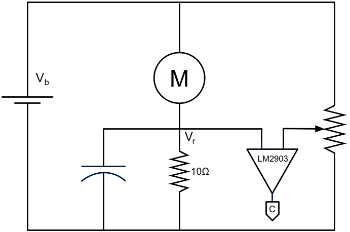
Here’s how it works: Power flows through the motor to the resistor — for a larger motor you’d want a smaller resistor. The capacitor serves to short the spike to ground. Thus, Vr is a touch less than Vb, with a small sinusoidal wave on top. The variable resistor on the right serves to provide a comparison voltage equal to the base voltage across the resistor. The LM2903 is a comparator. It compares that base voltage with the sinusoidally rippling voltage; when the sinusoidal voltage exceeds the base voltage, the comparator switches states. Thus, the comparator emits a stream of digital pulses with frequency concomitant with the motor speed. It’s not exactly equal to the motor speed because the motor has an unknown number of coils generating the sinusoisdal back EMF. I’ll have no problem calibrating it later. I send the output of the LM2903 to a counter.
The values of the components are dependent upon the motor’s characteristics. Different motors require different values. In my case, the voltage divider is 300K ohms, the capacitor is 47 microfarads. Oh, and I forgot to show the pullup resistor (10K) for the output of the LM2903. Another thing: the battery driving the motor is 12V, but I used 5V from a voltage regulator for the voltage divider, the power to the LM2903, and the counter.
This is all rather mundane stuff, but for one startling fact: this circuit is not on the Internet. Perhaps my search skills are not up to the task, but extensive searching for speed measuring of DC motors using back EMF turned up a zillion circuits using the conventional disk method, and only two references to the method I am using, both from the same author. These pages dates back to 2001, and both of them warn that this method is unreliable because of the voltage spikes. I must confess that I don’t understand the circuit proposed by the author; he puts two capacitors on the signal path, one in series and one to ground. It would seem to me that he can’t make up his mind how he wants to condition the signal. Nor does he use a voltage comparator; he simply drives a transistor to saturation. It seems that he is triggering the output on the spike rather than the sinusoidal curve that I utilize.
Perhaps I have missed something important. Perhaps my design will explode if it gets too hot. But I’ve run it for several hours and it seems to be producing excellent results. Perhaps it’s just that the motor I’m using is small enough to permit me to get away with this design. Perhaps a heavy load on the motor will cause it to draw more current, which will increase Vr and cause the counter to miscount. I tried loading down the motor and saw no effect on the count results.
Here are four hypotheses to explain my failure to locate any discussions of this design. I list them in order of my estimate of the likelihood that they are correct.
1. My search of the Internet was inadequate and I failed to find it.
2. The design is seriously flawed and so nobody discusses it.
3. The design just happens to work with my motor, and won’t work on most motors.
4. I am the only person on the planet who, in 40 years, has figured this out.