
April 27th, 2008
In 1972, I conducted an experiment to observe the Geminid meteor shower. I had a top-notch observer, Bill Goss, but even the best observer has periods of greater or lesser sensitivity. My problem was, how do I measure the variation in his sensitivity?
I set up an octagon of 6 foot poles centered on Bill’s eye position. Around the circumference of that octagon, at a height of six feet, I strung pairs of support wires. In the center of each segment, I placed a pair of tiny light bulbs spaced about 4 inches apart. This layout is presented in Figure 1.
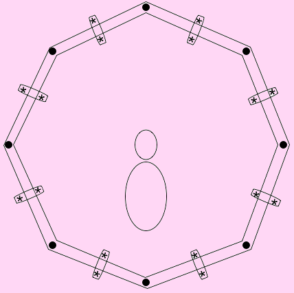
Figure 1 Diagram of observing layout
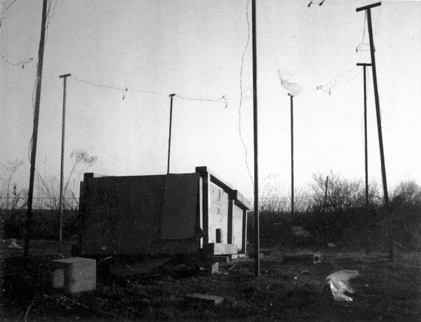
Figure 2 Ground level view of the system
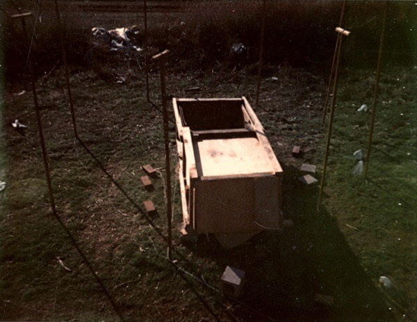
Figure 3 Looking down on the system
From Bill’s position, these pairs of lights stood near the periphery of his vision, with the pair arranged radially. If the two lights flashed in rapid sequence, he would see the optical equivalent of a meteor. Bill had two pushbuttons, one for Geminids and one for test flashes; whenever he saw something, he pressed the appropriate button. Hence, I could measure his sensitivity by presenting him with random flashes of one of the eight light pairs and recording whether he saw the flash.
But this was not the true kluginess of the experiment; that came from a deeper problem. I needed a way to present Bill with flashes of randomly chosen lights at randomly chosen times. Nowadays, this is a trivial task with a small computer; back then, it was a problem of such daunting magnitude as to require the deployment of genius-level klugecraft.
Being a physics undergraduate (this project was my senior thesis), I knew that a classical gas shows random behavior at a microscopic level. Therefore, I needed only to build a macroscopic classical gas -- one with very large molecules. Ball bearings would do nicely. I chose rather large ball bearings (3/8”) for reasons that will become apparent later.
Now, a classical gas doesn’t need to operate in three dimensions; theoretically, a two-dimensional classical gas is just as random as a 3D one. So my container was simply a piece of of plywood with 3/4” lathes marking out the boundaries of the container, as shown below:
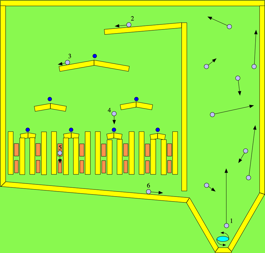
This entire assembly was laid out on a piece of plywood and tilted at a shallow angle so that the ball bearings would roll downwards.
The starting point for this crazy device is the blue rotor at the bottom right. It spun rapidly, imparting high velocity to any ball bearing that rolled down into it. In the drawing, blue rotor has just struck the purple ball bearing marked “1”, which is now shooting upwards at high velocity. It will collide with the other ball bearings, speeding them up and energizing the entire gas. Every now and then one of the ball bearings would by random chance exit the chamber at its upper left (Ball bearing “2”). I was able to control the rate at which ball bearings exited the chamber by adjusting the number of ball bearings in the chamber and the speed of the rotor. (The elliptical rotor was forced upon me when experimentation showed that a diamond-shaped rotor wore out too quickly.)
Once a ball exited the chamber, it rolled down the ramp and fell off it onto a nail indicated by a dark blue circle. It would randomly bounce either to the right or the left. Of course, getting true random performance out of the system required a great deal of fine-tuning. Adjustments in probabilities were effected by sanding selected patches to greater smoothness than others, as well as by slightly bending the nails that formed the pivots. This is illustrated by ball “3”.
After the ball bounced off the top nail, it would proceed to the next layer, where another nail awaited it. Then it bounced down to a third layer where yet another nail awaited it. The result of all this bouncing was that the ball could end up going down any one of the eight exit chutes at the bottom.
In rolling down the exit chute, the ball would roll over the two handmade microswitches represented by the orange rectangles. These consisted of two strips of copper separated at one end by a single layer of electrical tape, as shown below:
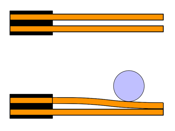
When the ball bearing rolled over the microswitch, contact was made and current was sent to the appropriate light. Again, considerable adjustment was required to establish the ideal duration and separation of the light flashes of the individual lights.
It had been my intention that the entire recording process would be made automatic by sending different tones to a tape recorder depending upon the signal (which lamp triggered and which button pressed by the observer). Unfortunately, I was unable to figure out how to build the oscillators of sufficient frequency discrimination to do the job. I therefore sent the outputs to a set of light bulbs inside tomato cans covered with wax paper and employed several friends to stand over the assembly with microphone, intoning “Number 3 -- he saw it; Geminid; Number 7 -- he didn’t see it” all through the night. Inasmuch as this was finals week, their services were especially appreciated.
On the night of December 13-14, 1972, I employed this device to record data on the Geminid meteor shower. The only serious hitch arose when Tornky our pet duck chose to make a nest in the plexus of wires at the base of the poles where all the connections were made. Somewhere in our data tapes you can hear me screaming “Tornky, you stupid duck, get out of there!” followed by much indignant quacking.
Otherwise, the system worked perfectly.